8 Global Locations
MORE INFOPart 1: Static Modelling Workflow
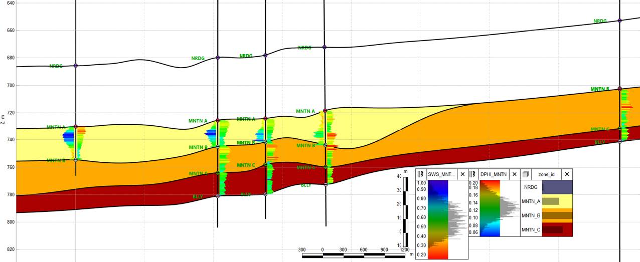
Well correlation was performed to interpret well tops for the Nordegg, Montney A, B, and C, and Belloy formations. Structural surfaces were generated and used to construct a structural model (IJK = 50x50x1m). Petrophysical calculations were carried out using raw logs to create porosity logs (from density) as well as water saturation logs (Simandoux, MNTN A zone only) to be interpolated through the model. Porosity calculated from logs had a 0.86 correlation coefficient with porosity measured in core (Montney A).
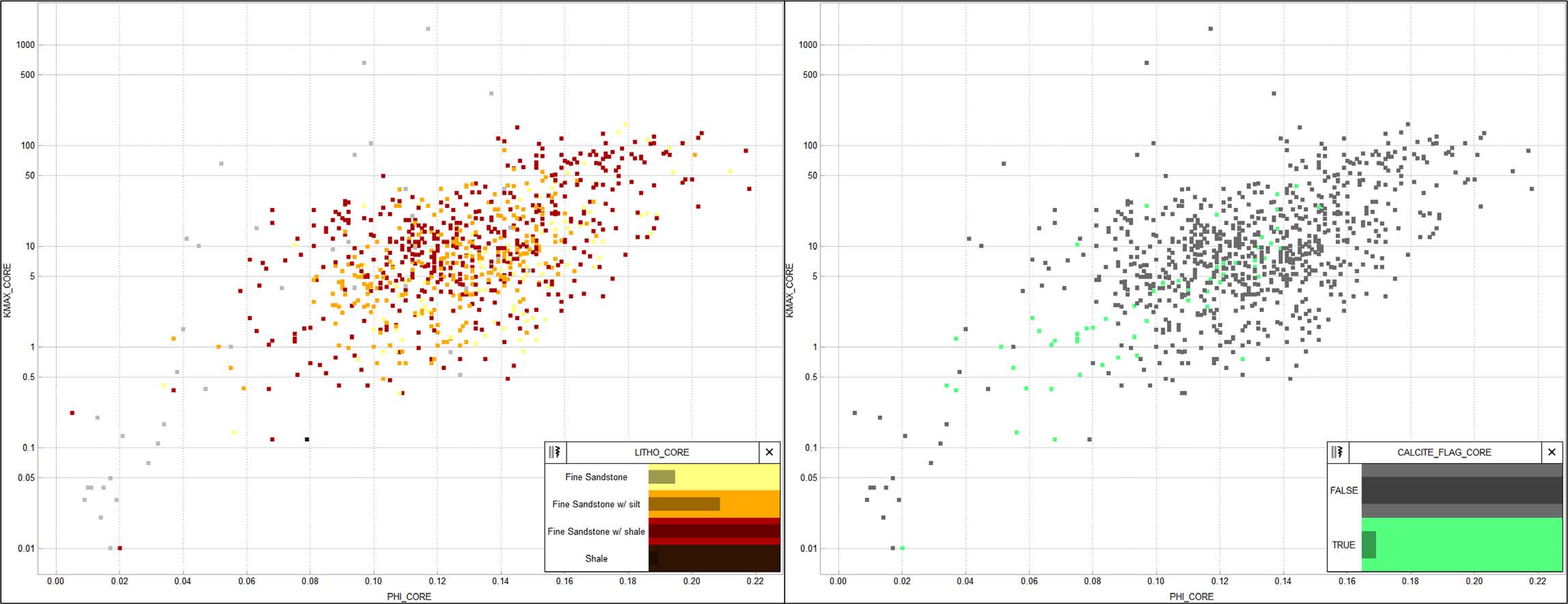
Core data analysis was performed to determine any relationship between lithological and cement descriptions and petrophysical measurements. There was found to be little relationship between core lab facies descriptions and porosity and permeability measurements. Facies descriptions were lumped to simplify any potential modeling. Further analysis revealed a relationship between the presence of calcite cement and lower porosity and permeability measurements.
Core data was only available for 16 of the 91 wells in the project, so the calcite flag would need to be extrapolated across as many wells as possible. Analysis of wells logs revealed a relationship between RHOB, DTC, and calcite flagged in core. The graphical filtering tool was used to extract a discrete well log from a cross plot of these logs and core data to be upscaled into the model. RHOB and DTC were both upscaled into the model and geostatistically interpolated. A calcite flag property was extracted from these two properties using the graphical filtering tool.
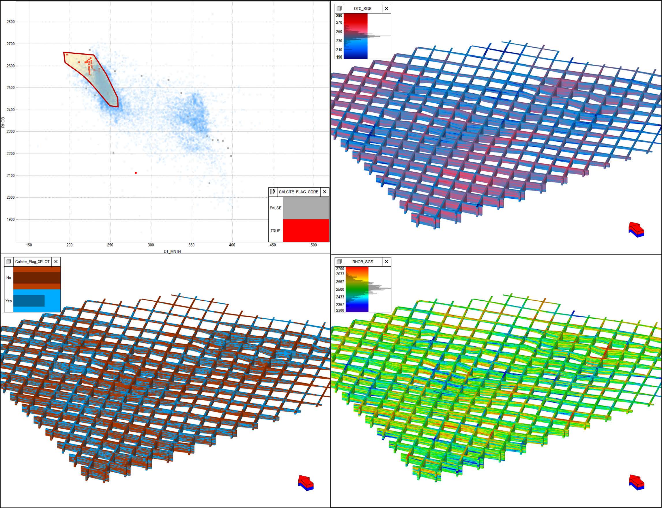
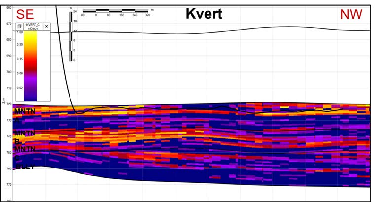
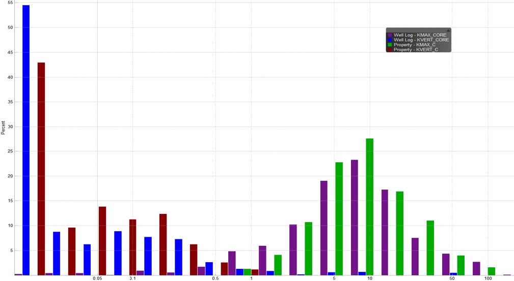
Porosity was interpolated stochastically through the model using variograms generated separately for calcite and non-calcite facies, as well as by zone. Porosity and permeability are known to influence the distribution of saturations in this reservoir; therefore, water saturation was interpolated stochastically and co-kriged with the porosity property using a correlation coefficient of -0.51, taken from core and log analysis. Kmax was calculated from the porosity property using the equation y=0.262*e (26.7x), taken from the correlation of Kmax and PHI in core. K90 and Kmax in core have a 0.98 correlation coefficient and are assumed to be equal for the purposes of this study. Kvert was calculated from Kmax using the amended equation y=if(x<7.5 then: 0.01, else: 0.008*x-0.0399) to best fit a complex non-linear relationship.
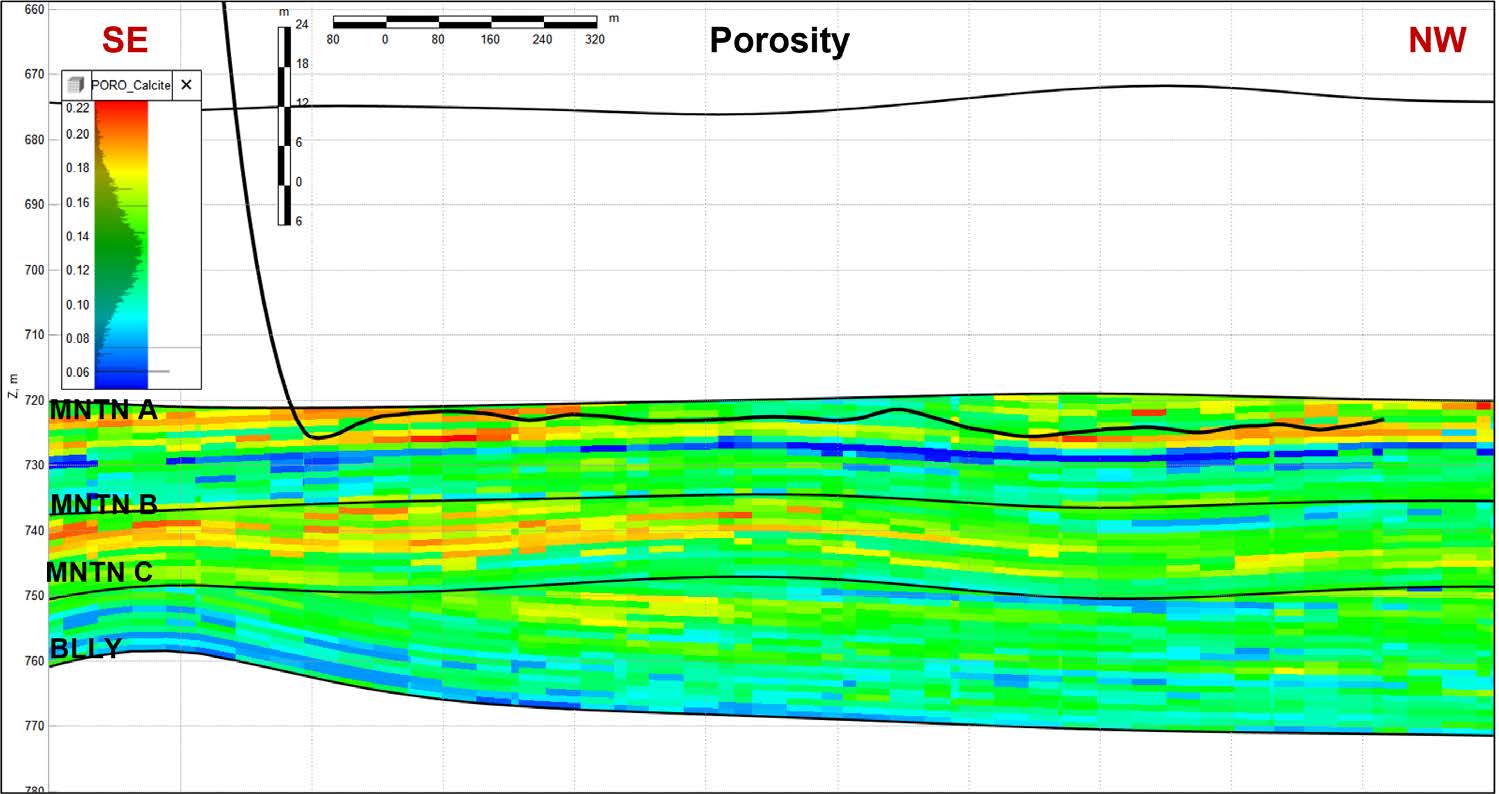
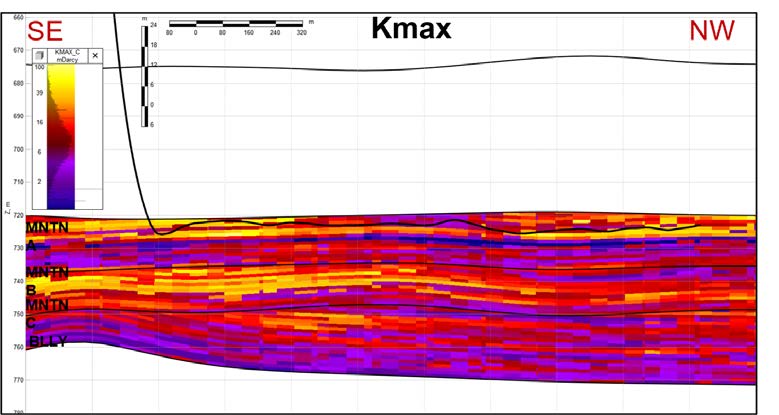
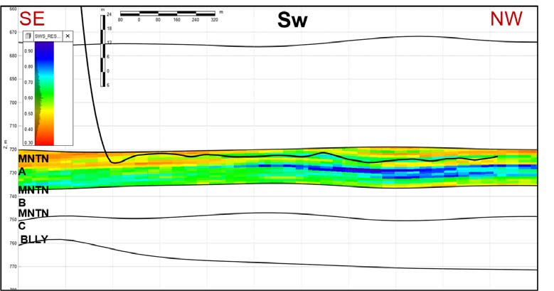
Outcome:
A model was generated integrating petrophysics from raw logs, core analysis and description, in addition to well correlation and interpreted subcrops. Every step of the process was completed within tNavigator, including data analysis and trend extraction. Processes were automated in a workflow within tNavigator for maximum efficiency and repeatability as new data is gathered and new interpretation is introduced to the model.
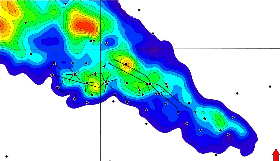
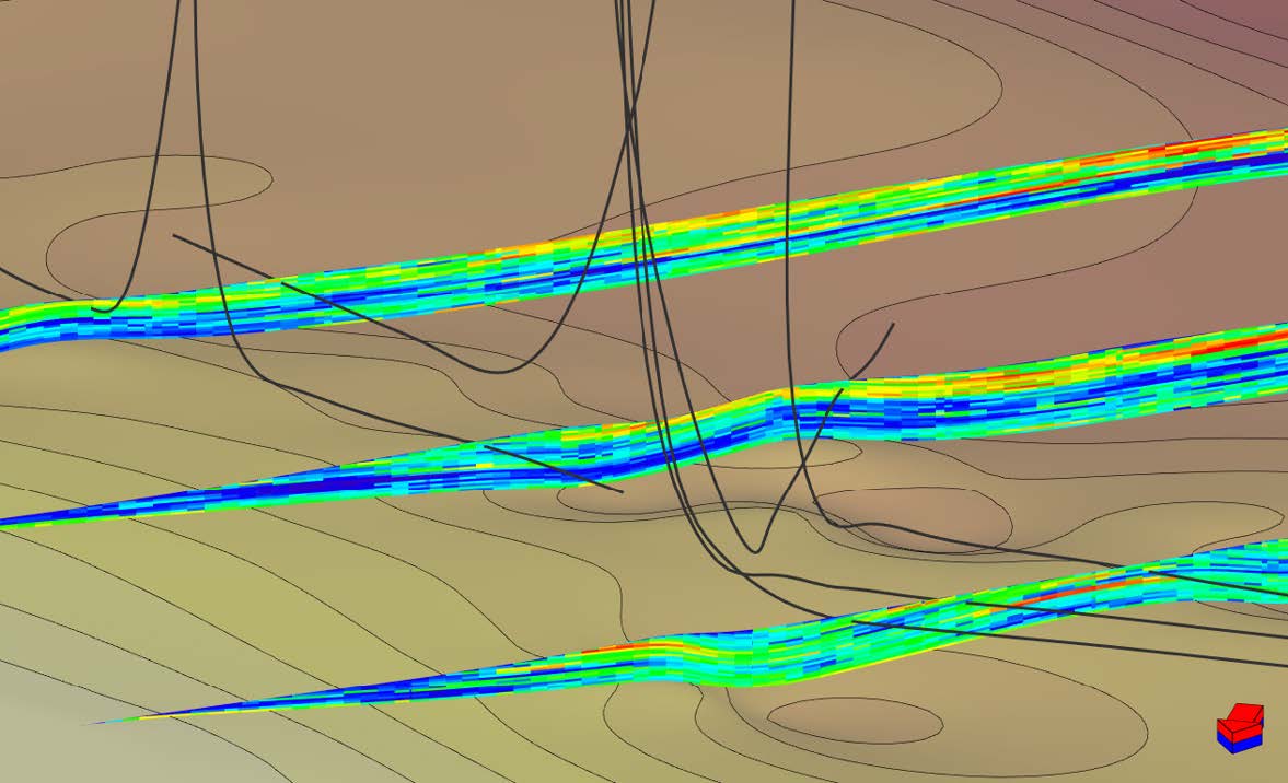
This model is suitable for volumetric calculations, static uncertainty analysis from volumetrics, proposed well positioning and geosteering, as well as fracture and reservoir simulation.
Keep reading to learn how the static model was carried into the next stage of the project, where dynamic properties including PVT analysis and fracture tables were added to the model to prepare it for simulation. In the final stage, hardware setups were tested and compared to find the solution that provided the best run time performance.
Part 2: Dynamic Model Test
A dynamic model was built based on the Sunset A geomodel. The objective was to test its usability for history match and production forecasting. Most procedures to load dynamic data follows the standard practices outlined in tNavigator tutorials, guides and manuals, which demonstrates that real field data can be easily processed by Model Designer. This section will highlight three important features in this project: PVT, fracture table and performance.
1. PVT
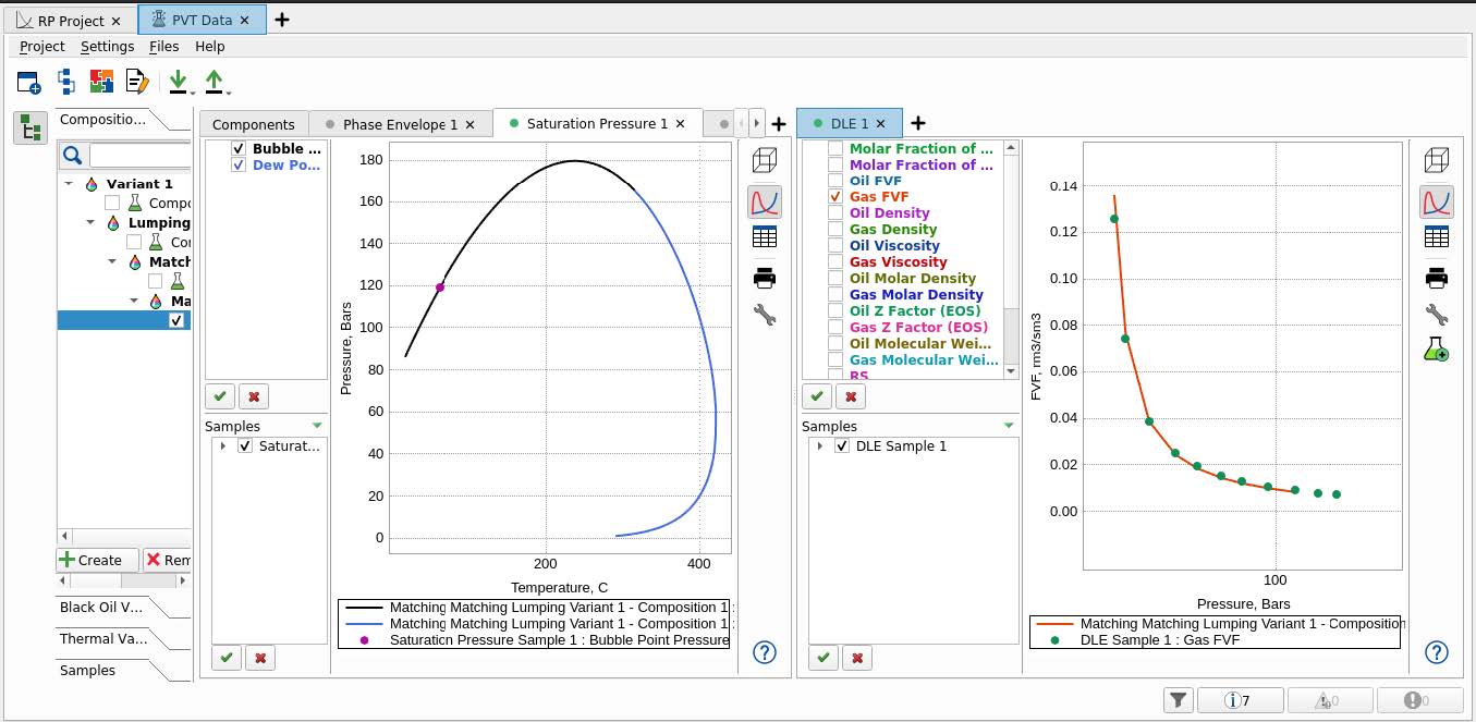
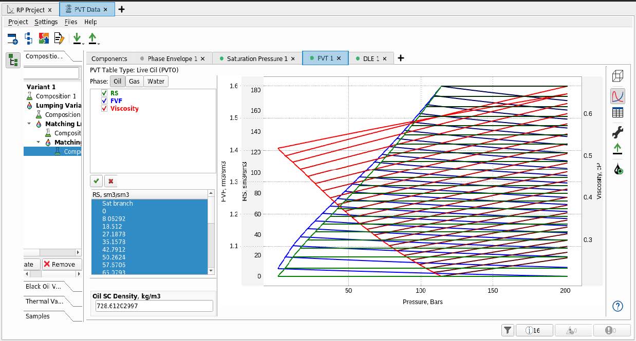
Enercapita supplied a laboratory PVT report from a representative sample. Firstly, the composition and reservoir temperature was loaded, which allowed calculations of saturation pressure and phase envelope plots to QC the EOS. The differential depletion test results were loaded and compared with EOS results. Any matching differences were resolved by performing lumping and regression of pseudo-component properties. A good EOS match was obtained and a black oil version of the EOS was created. This black oil version was used in the dynamic model test. A common practice is to use black oil versions during the early simulation stages and switch to compositional PVT once the model is QC’d, updated and stabilized. Figure 8 shows the EOS match obtained with lab PVT data, `Figure 9 shows the equivalent black oil PVT used during the dynamic model test.
1. Fracture Table
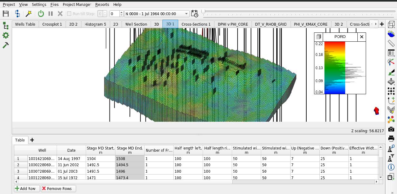
Modeling unconventionals in tNavigator is very common, with multiple tools available to simplify the task. One of these tools is Fracture Tables, in which the hydraulic fracture basic data can be entered in a very intuitive table format, for a large number of wells at once. The fracture table is automatically synchronized with 3D view for an easy QC of data. Figure 10 shows a 3D view of the hydraulic fractures and its respective fracture table. The fracture table for this project has 115 rows.
3. Performance
Hardware is constantly moving towards faster and more efficient processors. Traditional CPUs are being surpassed by newer GPU technology. tNavigator has adapted to new technologies and is built to leverage the maximum computing power available – for both static & dynamic workflows. This often results in quicker model run-times and cost savings to our users.
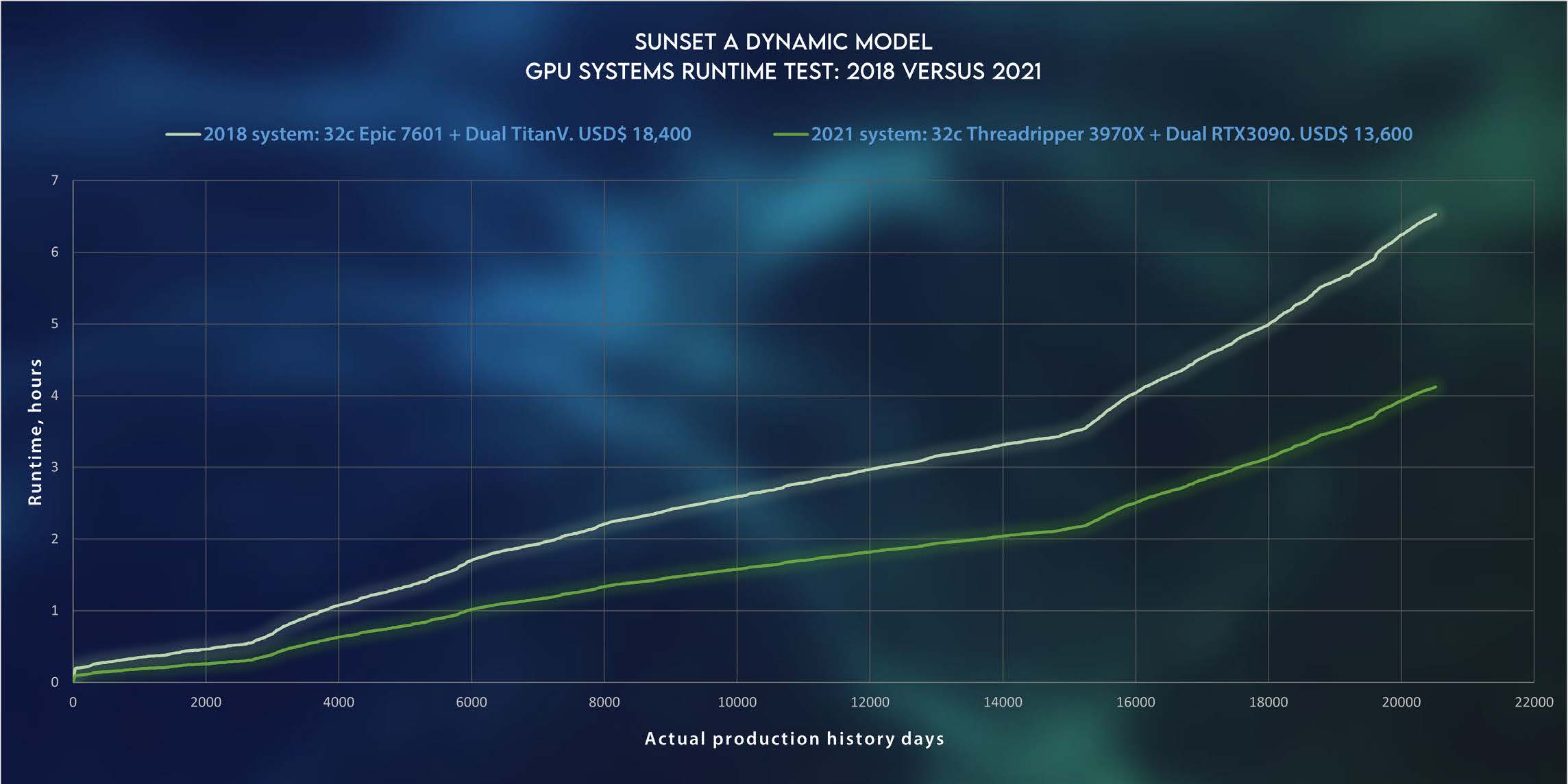
The Sunset A dynamic model was tested with two GPU system vintages: 2018 versus 2021. Figure 11 shows the runtime results. It can be noticed the important runtime decrease and cost decrease of using up-to-date GPU technology for reservoir simulations. Further improvements could be achieved by numerical tuning and quality check of physical inputs.
